Heating Down to -22°F at 80% Efficiency
 Perfect for New Construction and Retrofits
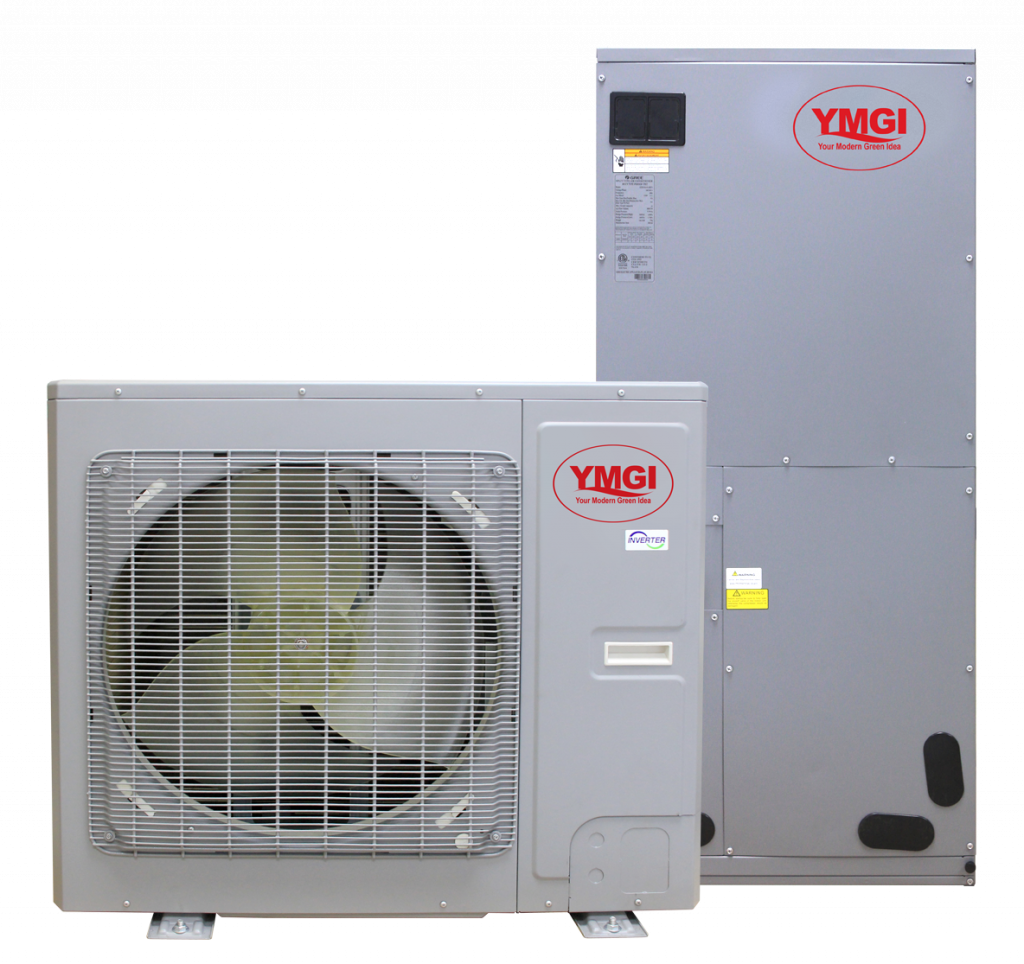
Designed to replace existing central air systems with air handlers. Easily adapts to your existing duct work. Great for new installations where duct work is preferred. All electric heat pump replaces gas furnaces and AC coils to save energy and lower operation costs.
Install Horizontally or Vertically
UC Unit can be installed in a vertically or horizontally, giving you the flexibility to install according to your desire or need. Horizontal mounting is a great solution for installations with minimum space, like attics or crawlspaces.
YMGI’s Unitary 18 SEER 24V DC inverter condensing unit, a newly designed high efficiency heat pump targeted at the North America market. Can be used anywhere a central air system can. This ducted system is great for system replacements in homes or buildings that use ducts for heating and cooling.
The outdoor unit uses an inverter compressor with efficiency ratings of up to 20 SEER and 10.5 HSPF. Uses YMGI’s two-stage compression EVI technology, only small performance declines occur when ambient temperatures are extremely hot or cold area.
Ultra Heating: Powerful heating at low ambient temperatures:
- 100% Heating Capacity down to -5°F(-20°C) *
- 78% Heating Capacity down to -22°F(-30°C) *
Ultra Cooling: Powerful cooling at high ambient temperatures:
- 100% Cooling Capacity up to 115°F(46°C)*
- 78% Cooling Capacity up to 130°F(54°C)*
- Compatible with most standard 24V thermostats on the market.
- Inverter technology, quieter, more comfortable, more energy efficient.
- Installation is similar to traditional air conditioner. Little training needed for experienced installers.
- Compact space saving design; perfect for installation with limited space.
- 10 Year Warranty on Compressor
- 5 Year Warranty on parts
*Notes: Test results based on condenser VRUO-2436HP-U2B(54) and air handler VRUI-24UC-M2B(54).
Outdoor Unit Condenser Specifications

Throttling Method
Electronic Expansion Valve Electronic Expansion Valve
| Model | VRUO-2436HP-U2B(54) |
VRUO-4860HP-U2B(54) | ||||
| Outdoor Unit | Type | Condenser | Condenser | |||
| Total Capacity | Cooling | Btu/h | 24000 | 48000 | ||
| Heating | Btu/h | 24000 | 48000 | |||
| EER / C.O.P | Btu/h.W | 12.50/14.33 | 11.00/12.28 | |||
| SEER / HSPF | Btu/h.W | 20.00/10.50 | 18.00/10.50 | |||
| Energy Class | – | / | / | |||
| Electrical Data | Power supply | V-Hz-Ph kW | 208/230-60-11.92 | 208/230-60-14.36 | ||
| Power input1 | Cooling | kW | 1.92 | 4.36 | ||
| Heating | kW | 1.67 | 3.91 | |||
| Rated Power input 2 | Cooling | kW | 3.20 | 6.40 | ||
| Heating | kW | 4.20 | 6.80 | |||
| Input current1 | Cooling | A | 7 | 18 | ||
| Heating | A | 7 | 18 | |||
| Rated current2 | Cooling | A | 13 | 30 | ||
| Heating | A | 17 | 31 | |||
| Max. Overcurrent Protection | A | 35 | 45 | |||
| Min/Max Voltage Level (H/M/L)* | vdB (A) | 187/253 | 187/253 58 | |||
| Sound Pressure | dB (A) | 55 | 58 | |||
| Sound Power Level (H/M/L)* | dB (A) | 65 | 68 | |||
| Refrigerant | R410A Charge | oz | 148.15 | 220.46 | ||
| Compressor | Manufacturer | Gree | Gree | |||
| Model | — | QXFT-F310zN450 | QXAU-F516zX440A | |||
| Type | — | Inverter Rotary | Inverter Rotary | |||
| Quantity | – | 1 | 1 | |||
| Capacity | W | 10600 | 17800 | |||
| Power Input | W | 3680 | 6000 | |||
| Run Capacitor | µF(MFD) | / | / | |||
| Rated Load Amp (RLA) | A | 7 | 13 | |||
| Locked rotor Amp (L.R.A) | A | / | / | |||
| Thermal protector | – | Internal | Internal | |||
| Crankcase | W | 40 | 40 | |||
| Refrigerant oil | Type | – | FW68DA or equivalent | FW68DA or equivalent | ||
| Charge Volume | L | 1.12 | 1.35 | |||
| Air Flow Volume | CFM | 3000 | 4700 | |||
| Fan Motor | Model | – | B-SWZ150A | SWZ150D | ||
| Drive Type | – | Direct Drive | Direct Drive | |||
| Speed (H/M/L)* | rpm | 700 | 800 | |||
| Power Output | HP | 0.2 | 1/5 x 2 | |||
| Full Load Amp(FLA) | A | / | / | |||
| Insulation class | – | B | B | |||
| Safe class | – | IP44 | IP44 | |||
| Capacitor | uF | / | / | |||
| Fan | Quantity / Type | 1 / Axial-flow | 2 / Axial-flow | |||
| Diameter | Height | inch | Ø21.65 | 7 | Ø20.47 | 6 | |||
| Condenser | Material | – | Inner Groove Copper Tube-Aluminum Fin | Inner Groove Copper Tube-Aluminum Fin | ||
| Face Area | sq.ft | 1.7 | 1.7 | |||
| Pipe Diameter | in. | Ø5/16” | Ø5/16” | |||
| Number of rows | 2 | 3 | ||||
| Tube pitch(a)x row pitch(b) | mm | 22×19.05 | 22×19.05 | |||
| Fins per Inch(FPI) / Fin type | – | 18 / Ripple | 17 / Ripple | |||
| Number of circuits | – | 5 | 9 | |||
| Length(L) x Height(H) x Width(W) | in | 45.43” × 31.18” × 1.5” | 37.95” × 51.97” × 2.25” | |||
| Permissible Excessive Operating Pressure for the Discharge Side | PSIG | 550 | 550 | |||
| Permissible Excessive Operating Pressure for the Suction Side | PSIG | 250 | 250 | |||
| Operation temp | Cooling | °F | 5 °F ~129.2 °F | 5 °F ~129.2 °F | ||
| Heating | °F | -22 °F ~75.2 °F | -22 °F ~75.2 °F | |||
| Defrosting Method | – | Automatic Defrosting | Automatic Defrosting | |||
| IsolationMoisture Protection | — | IIPX4 | IIPX4 | |||
| Overload Protector | / | / | ||||
| Dimensions | ||||||
| Outline dimensions (W×D×H) | in. | 37”×18.11”×32.28” | 39.37”×14.57”×53.74” | |||
| Package dimensions (W×D×H) | in. | 42.64”×22.56”×38.31” | 45.39”×19.41”×59.25” | |||
| Weight | ||||||
| Net Weight | lbs. | 217.16 | 308.65 | |||
| Gross Weight | lbs. | 240.30 | 337.31 | |||
| Connection Pipe | ||||||
| Valve Connection Type | – | Screw Connection or Solder Connection | Screw Connection or Solder Connection | |||
| Length | ft. | 25 | 25 | |||
| Gas additional charge | g/m | 0.3225 | 0.3225 | |||
| Outer Diameter | Liquid Pipe | in. | 3/8″ | 3/8″ | ||
| Gas Pipe | in. | 3/4″ | 3/4″ | |||
| Max Distance | Height | ft. | 50’ | 50’ | ||
| Length | ft. | 100’ | 100’ | |||
Indoor Unit Air Handler Specifications

| Parameter | (Unit) | VRUI-24UC-M2B(54) | VRUI-36UC-M2B(54) | VRUI-48UC-M2B(54) | VRUI-60UC-M2B(54) | |||
| Type | Airhandler | Airhandler | Airhandler | Airhandler | ||||
| Power supply | V-Hz-Ph | 208/230-60-1 | 208/230-60-1 | 208/230-60-1 | 208/230-60-1 | |||
| Electrical Data |
Power input1 | Cooling | kW | 0.14 | 0.18 | 0.31 | 0.42 | |
| Heating | kW | 0.14 | 0.18 | 0.31 | 0.42 | |||
| Input current1 | Cooling | A | 1.00 | 1.36 | 2.22 | 2.92 | ||
| Heating | A | 1.00 | 1.36 | 2.22 | 2.92 | |||
| Max. Overcurrent Protection | A | 15 | 15 | 15 | 15 | |||
| Min/Max Voltage |
Min/Max Voltage (V) |
V | 187/253 | 187/253 | 187/253 | 187/253 | ||
| Power cord spec | Electrical Conduit Size (Inch) | mm2xpcs | / | / | / | / | ||
| Fuse (A) | A | / | / | / | / | |||
| Sound Pressure Level (SS/H/M/L)* |
dB (A) | 45 | 47 | 50 | 51 | |||
| Sound Power Level (SS/H/M/L)* |
dB (A) | 55 | 57 | 60 | 61 | |||
| Refrigerant | Type | – | R410A | R410A | R410A | R410A | ||
| Control | – | Thermal expansion valve | Thermal expansion valve | Thermal expansion valve | Thermal expansion valve | |||
| Air Flow Volume(rated EXP) |
CFM | 940 | 1000.45 | 1470 | 1600 | |||
| External Static Pressure |
Rated | Pa | 25 | 37 | 50 | 50 | ||
| InWg | 0.1 | 0.148 | 0.2 | 0.2 | ||||
| Range | Pa | 0~100 | 0~100 | 0~100 | 0~100 | |||
| InWg | 0~0.4 | 0~0.4 | 0~0.4 | 0~0.4 | ||||
| Fan Motor | Model | – | FGZ370B | FGZ370B | FGZ750B | FGZ750B | ||
| Drive Type | – | Direct drive | Direct drive | Direct drive | Direct drive | |||
| Speed | rpm | 750 | 820 | 850 | 930 | |||
| Power Output | W | 1/2 | 1/2 | 1 | 1 | |||
| Full Load Amp(FLA) | A | 2.10 | 2.10 | 3.20 | 3.20 | |||
| Capacitor | uF | / | / | / | / | |||
| Fan | Quantity / Type |
1 / Centrifugal |
1 / Centrifugal |
1 / Centrifugal |
1 / Centrifugal |
|||
| Diameter-Height | in. | Ø10.24-9.69 | Ø10.24-9.69 | Ø10 7/8” – 11 1/4” |
Ø10.87-11.26 | |||
| Material | – | Inner groove copper tubeAluminum fin | Inner groove copper tubeAluminum fin | Inner groove copper tubeAluminum fin | Inner groove copper tubeAluminum fin | |||
| Face Area | sq.ft | 4.09 | 4.09 | 5.49 | 5.49 | |||
| m2 | 0.38 | 0.38 | 0.51 | 0.51 | ||||
| Pipe Diameter | in. | Ø9/32 | Ø9/32 | Ø3/8 | Ø3/8 | |||
| Evaporator | Number of rows | 4 | 4 | 4 | 4 | |||
| Tube pitch(a)x row pitch(b) | in. | 3/4”×1/2” | 3/4”×1/2” | 1” × 7/8” | 1”× 7/8” | |||
| Fins per Inch(FPI) / Fin type | 16 / Hydrophilic-window |
16 / Hydrophilic-window |
14 / Hydrophilic-window |
14 / Hydrophilic-window |
||||
| Number of circuits |
12 | 12 | 12 | 12 | ||||
| Length(L) x Height(H) x Width(W) |
in. | 16 11/32” × 2” ×18” | 16 11/32” × 2 “ × 18” |
16 11/32” × 3 15/32 “ × 24” | 16 11/32” × 3 15/32 “ × 24” | |||
| Operation temp |
Cooling | °F | 64.4°F ~80.6°F | 64.4°F ~80.6°F | 64.4°F ~80.6°F | 64.4°F ~80.6°F | ||
| Heating | °F | 68°F ~80.6°F | 68°F ~80.6°F | 68°F ~80.6°F | 68°F ~80.6°F | |||
| Drainage Connection Size (Outer Diameter×Wall Thickness) |
in. | Ø1”× 1/16” | Ø1”× 1/16” | Ø1” × 1/16” | Ø 1“ × 1/16” | |||
| System Operation Control | Wired controller | Wired controller | Wired controller | Wired controller | ||||
| Dimensions | ||||||||
| Outline dimension (W×D×H) | in. | 21 1/4” × 21 1/4” × 48 3/16” | 21 1/4” × 21 1/4” × 48 3/16” | 24 13/16” × 21 1/4” × 57” | 24 13/16” × 21 1/4” × 57” | |||
| Package dimension (L×W×H) | in. | 26” × 23 3/4”× 50 3/8” | 26” × 23 3/4”× 50 3/8” | 27 9/32” × 26” × 59 3/8” | 27 9/32” × 26” × 59 3/8” | |||
| Liquid Pipe | in. | 3/8″ | 3/8″ | 3/8″ | 3/8″ | |||
| Gas Pipe | in. | 3/4″ | 3/4″ | 3/4″ | 3/4″ | |||
| Weight | ||||||||
| Net Weight | lbs | 156.53 | 156.53 | 202.83 | 202.83 | |||
| Gross Weight | lbs | 169.76 | 169.76 | 218.26 | 218.26 | |||
Notes:
-
-
- The cooling capacity stated above is measured under following conditions:
Indoor Condition: 27 °C (81°F)DB/19°C(66.6°F) WB.
Outdoor Condition: 35 °C (95.4°F)DB/24°C(75.6°F) WB. - Noise is tested in the semi-anechoic room, so it will
be slightly higher in operation due to environmental change. - “1” is tested under standard conditions.
“2” is tested under rated conditions according to CE/ - * Fan different speed
- The cooling capacity stated above is measured under following conditions:
-

